Hammond Organ consoles equipped with vibrato differ from tremulant models in the omission of the tremulant switch, tremulant control, and non-vibrato preamplifier, and in the addition of the vibrato line box, scanner, vibrato switch, and vibrato preamplifier. Three degrees of vibrato are available and also a different degree of chorus or celeste effect with each of the three degrees of vibrato. Console models with the suffix “2” and “3n in their model designation have the selective vibrato feature, with tilting control tablets permitting the player to place the vibrato effect on either manual or both.
PRINCIPAL OF OPERATION
The vibrato effect is created by a periodic raising and lowering of pitch, and thus is fundamentally different from a tremolo, or loudness variation. It is comparable to the effect produced when a violinist moves his finger back and forth on a string while playing, varying the frequency while maintaining constant volume.

The Hammond Organ vibrato equipment (see simplified block diagram, Fig. 1) varies the frequency of all tones by continuously shifting their phase. It includes a phase shift network or electrical time delay line, composed of a number of low pass filter sections, and a capacity type pickup or scanner, which is motor driven so that it scans back and forth along the line.
Electrical waves fed into the line are shifted in phase by each line section (the amount per section being proportional to frequency), so that at any tap on the line the phase is retarded relative to the previous tap.
The scanning pick-up traveling along the line will thus encounter waves increasingly retarded in phase at each successive tap, and the signal it picks up will continuously change in phase. The rate at which this phase shift occurs will depend on how many line sections are scanned each second.
Since a cycle is equivalent to 360 electrical degrees, a frequency shift of one cycle occurs for each 360 electrical degrees scanned per second. For example if the scanner passes over the line at such a rate that 3600 electrical degrees are scanned each second, there will be a frequency change of 10 cycles.
For the widest vibrato, the whole line is scanned from beginning to end in about 1/14 second, and this rate of change of phase causes about 1-1/2% decrease in frequency. Note that the frequency remains constantly 1-1/2% low as long as the moving pick-up retards the phase at a constant rate.
Since the pick-up sweeps from start to end of the line and then back, it increases the frequency by an equal percentage on its return trip, the average output frequency remaining equal to the input frequency. The exact amount of frequency shift depends not only on the amount of phase shift in the line but also on the scanning rate. This rate, however, is constant because the scanner is driven by the synchronous running motor of the organ.
The degree of vibrato (or amount of frequency shift) may be varied by a switch (not shown in Fig. 1) which causes the whole line to be scanned for #3 (wide) vibrato, about half of it for #2, and about one third for #1.
A vibrato chorus effect, similar to the effect of two or three slightly out-of-tune frequencies mixed together, is obtained when the vibrato output signal is mixed with a portion of signal without vibrato. For vibrato chorus, part of the incoming signal appears across the vibrato line and the rest across a resistor in series with the line. As the vibrato effect is applied to the part of the signal appearing across the line but not to the part appearing across the resistor, the combination produces a chorus effect. For normal vibrato, this resistor is short-circuited.
In selective vibrato consoles the vibrato effect can be applied to either manual separately or to both at once.
CONSTRUCTION OF COMPONENTS
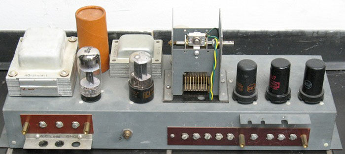
Figures 2 and 3 show different models of the vibrato line box. Each of the air core inductance coils is connected with one or more condensers to form one filter section.
Figure 4 shows the construction of a typical vibrato switch. Some models differ in wiring and number of contacts, but all are similar in mechanical arrangement.
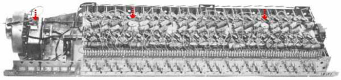
The scanner (fig. 5) is mounted on the main generator synchronous motor and driven at 412 revolutions per minute. It is a multi-pole variable condenser with 16 sets of stationary plates and a rotor whose plates mesh with the stationary ones. In figure 5B two sets of plates have been removed to show the rotor.
Signals coming from the line through the vibrato switch appear on the stationary plates and are picked up, one at a time, by the rotor. Connection to the rotor is made by carbon brushes as shown in figure 5A. Two brushes touch the sides of the contact pin and a third presses on the end, in order to eliminate the possibility of contact failure.


SCHEMATIC DIAGRAMS
Figures 6, 7, 8 and 9 show four different vibrato circuits which have been used in various models. As the components of different types are generally not interchangeable, it is important that model and serial number be furnished when ordering replacement parts.
Non-Selective Vibrato
Figure 6, used in all consoles with V in the model designation, has a 25 section vibrato line. It is wired (to minimize the number of compensated take-off points) so that the last part of the line is used for #1 vibrato. The vibrato switch has positions for three degrees of vibrato (V1, V2 and V3) with three “off” positions between them, and there is a separate vibrato chorus switch. A resistor connected to the “off” side of the chorus switch serves to maintain constant volume for the two switch positions. The switch is not intended to be left in its middle position.
The preamplifier used with this circuit is actually two separate cascaded amplifiers on one chassis, with the vibrato system connected between them. The first section drives the vibrato line, and the second section amplifies the signal picked up by the scanner. The “vibrato off” contact in the vibrato switch carries non-vibrato signal directly to the second section of the preamplifier. The complete schematic circuit of a console of this type is shown in Figure 7 of section 2, and preamplifier in Figure 6 of section 11.


Selective Vibrato
Figure 7, used in early selective vibrato consoles, also has a 25 section line. To obtain correct phasing of the “vibrato” and “no vibrato” channels, the first part of the line is used for #1 vibrato. The vibrato switch has no “off” position, and three vibrato chorus positions (C1, C2 and C3) are included in it as well as the three vibrato positions (V1, V2 and V3). The vibrato effect is turned on and off for each manual separately by means of “vibrato swell” and “vibrato great” tablets on the manual assembly.
The preamplifier used with this circuit, as indicated in Figure 9 of section 2, has two separate channels into which signals from the “vibrato great” and “vibrato swell” tablets are fed. The “vibrato” signal goes through a preliminary amplifier, through the vibrato system, and then into additional stages of amplification. The “no vibrato” signal also has a preliminary amplifier, but by-passes the vibrato system and goes directly into the following amplifier stages. The preamplifier alone is shown in Figures 20 and 20A of section 11.
Line with Resistor Dividers
The vibrato line box of Figure 8 employs resistors for voltage dividers at the compensated pick-off points instead of condensers. Otherwise this circuit is identical with that of Figure 7. The line boxes of these two types are interchangeable, and the scanners and switches are identical.
Coupled Line
Figure 9 shows the coupled-coil type of vibrato line box. It is smaller in size and requires only 18 sections to give the same amount of vibrato effect as the 25 sections previously used. The switch has one less contact in each position, and so neither the vibrato line nor the vibrato switch is interchangeable with earlier types. The preamplifiers are the same as those used with the circuits of Figures 7 and 8. The scanner has somewhat different wiring harness.
MODEL “M” VIBRATO SYSTEM
The vibrato system in the Spinet Model M Series is somewhat different from those described above. The line box is slightly smaller, the scanner is slightly different mechanically, and a completely different switching mechanism is used. A full description is given in the service books for these models.

Used in all models AV, BV, BCV, CV, DV, and RT Consoles

Model B-2 Consoles below serial number 37305
Model C-2 Consoles below serial number 38728
Model RT-2 Consoles below serial number 2031

Model B-2 Consoles serial number 37305 to 45900 and 46101 to 46154
Model C-2 Consoles serial number 38728 to 46961
Model RT-2 Consoles serial number 2031 to 2735

Model B-2 Consoles serial number 45901 to 46100, and 46155 and above
Model C-2 Consoles serial number 46962 and above
Model RT-2 Consoles serial number 2736 and above
Model B-3 and C-3 Consoles serial number 56000 and up
Model RT-3 Consoles serial number 4000 and up