
Several problems will occur with the Vibrato System.
- Vibrato sounds bad or uneven.
- Vibrato does not sound.
Most common is the problem with sounding uneven or choppy. This can be caused by the Delay Line or the Scanner.

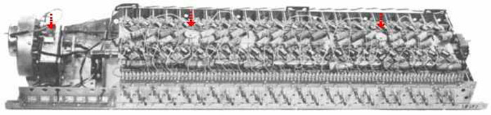
First, lets look at the Delay Line. It is made up of a series of low pass filters using inductors and capacitors. A failure of an inductor or capacitor will cause a section to fail and upset the overall sound. Usually the inductors don’t have problems. The most likely problem would be to open up. You can test this by shorting them out one at a time. If you hear an improvement on any inductor you short it may be bad.
For the capacitors you can parallel a good capacitor on each one in the line one at a time. Same thing. If paralleling one improves the sound then that one may be bad.(Open) If however a capacitor is shorted, you would have to remove it and replace it. Also, it’s a good idea to carefully check each connection from the Delay Line to the Scanner and to the Switches. Any broken wire will most surely cause a choppy sound.

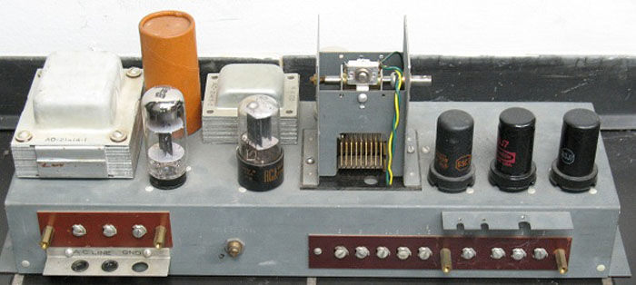
The Scanner can also have problems. One would be years of oil build up on the insulators used on each Plate. These can be viewed externally as fiber washers mounted on each screw terminal. They serve to insulate the signal on each plate from the case itself. If they look moist, they may be shorting the signal to ground and will need cleaning. Secondly, the metal case of the scanner can develop a fine “hair” growth from a process similar to corrosion which can short out the signal. In either case the sound can be profoundly effected and a rebuilding of the scanner would be prudent.
Our goal in rebuilding the Scanner is to clean out all the oil including the oil soaked insulators. Also to remove any metal “hair” formed on the scanner case.


First remove by unsoldering the wires on the end of the scanner harness near the upper left of the cabinet behind the start/run switches. Also remove the red and blue wire in the same harness from the delay line.
Now remove the two springs on the motor coupler which goes to the generator. Next, remove the four nuts holding the run motor to the generator. Carefully remove this assembly and bring it out toward you as far as you can. The motor wires are still connected so it will not come out all the way. This is a tight fit so just take your time, it will come out. If you like, you could remove the motor wires and the scanner output wire to be able to completely extract this assembly but in most cases, this is not necessary.

The next step is to separate the motor from the scanner. There are three screws here to remove. One of these screws also holds the oiling tub and great care is required to remove the felt and strings from the tub without breaking them.
With the scanner separated from the motor you want to open the scanner into the two halves. Before you do, this is a good time to mark the gap or break in the cable harness connected to the scanner. You will be removing this harness and this will aid in getting back into the same position.
Take a small sharp tool and put a scratch between the terminals marking the gap. Also put a scratch on the back half of the case near the first scratch so once separated, you can put the two halves back like they came apart. A marker may rub off when cleaning. Also remove the small cover on the back which protects the brushes. Remove these brushes at this time. Now, with the four screws of the scanner case removed, separate the two halves.
The back half will remain in the organ being still connected to the output cable. The other half can now be removed to service.

BE VERY CAREFUL not to bend the little contact which the brushes were mounted to on the rotor.
Begin to remove all the screws which holds the cable harness on. For each screw you will have a screw, lock washer, flat washer, round fiber washer, rectangle fiber washer, and the Plate.

All these parts are to be removed and soaked in a solvent. I use ACETONE but others will work. Also soak the harness briefly.

With a cloth soaked in solvent, wipe all the case sides of both halves inside and out.
All this can be done without removing the rotor being careful not to bend or break the contact located in the center of the rotor. In most cases it’s not necessary to remove it. However, if the rotor is stuck or you just want to be more thorough, you can remove it to free it up and service the bearing. The rotor has set screws holding it to the shaft. Also, the small round housing which holds the shaft can be removed for cleaning. No need to mark this because it has a key for assembly. Once all is clean place a very small drop of oil on the bearing at the shaft.
Assemble in the reverse order you disassembled. Be sure all parts are completely dry and clean. If you would like to go an extra step you could spray a clear coating on the case to prevent the “hair” from coming back. Otherwise, your service job may only last for 20 years.
To replace the wire harness take a screw and place it through a terminal on the harness watching to line it up with your scratch mark.

Now goes the lock washer, a flat washer, and then the round fiber washer. On the inside place a rectangular fiber washer over the small pins and then the plate. Tighten and repeat for all 16 screws.
Once this is complete, make sure the rotor spins freely and put the two halves back together lining up the second scratch mark. Replace the brushes on the rotor contact and replace the cover. Attach the scanner to the run motor and assemble the tub with the strings and felt.
This is the early version of the tub with the extended scanner oil string pipe.

This pipe should be removed or cut. The string that was there will be routed into the short pipe next to it.

This shows the new routing of the string.

Note: If any strings are broken then they need to be replaced before assembly. They are the lifeline for oiling.
Replace the motor/scanner assembly to the generator. Replace the wires to the upper left terminals.
Note: The two extra wires (red & blue) that exit the harness and go to the line box should be on your left when attached.
That’s it!


2 thoughts on “Servicing the Hammond Vibrato Scanner”
Why do you have to cut the long pipe and run the cotton thread through the other pipe?
Where can I find vibrato string?
Comments are closed.